Introduction
With the 16 digital channels available on Teledyne LeCroy’s HDO6000 Mixed Signal High Definition Oscilloscopes, users can gain deep insight into the behavior of digital busses by measuring and analyzing the circuit’s timing parameters. Let’s take a look at how easy it is to get started with digital measurements.
Procedure
For purposes of this demonstration, digital lines D0-D4 of the 16-channel digital lead set were connected to clock pins of varying speeds. Next, press the Dig (for Digital) button in the Vertical section of the front panel. This will activate the digital channels.
The measurement menu is accessible through the touch screen’s Measure pull-down menu. Next, we will specify the measurement parameter(s) and source(s) for the measurements. For this example, we’ll measure the pulse width and frequency. Other supported parameters include duty cycle, delay, and period
Under Measure in the Measure Setup dialog, touch tab P1. In the Select Measurement dialog, scroll down and touch Width. Next, touch the Source1 button in the Measure Setup dialog. Under category, select Digital Lines and touch the line of interest.
Select Measure Setup (Figure 1). Select tab P1 to set up measurement of the pulse width of D1.
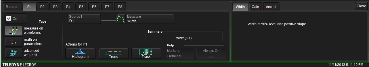
Figure 1:
The Measure Setup showing P1 set for measurement of width and P2 set for measurement of frequency
Repeat the above steps for P2, selecting Frequency in the Select Measurement dialog. Select the same digital line as for the width measurement.
Next, look to the far right in the Measure Setup dialog and turn on Statistics and Histicons by checking the boxes. Statistics and Histicons will provide insight into how the width and frequency values change over time (Figure 2).
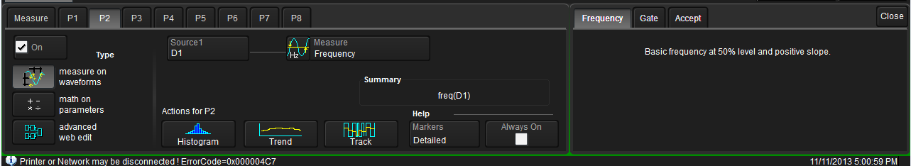
Figure 2:
Turning on Statistics and Histograms for measurements shows how those measurements change over time
Now, create a trace of all measured values by pressing the Trend button at the bottom of the parameter dialog (Figure 3). Tracks and Histograms can also be created use the shortcut buttons at the bottom of the parameter dialog.
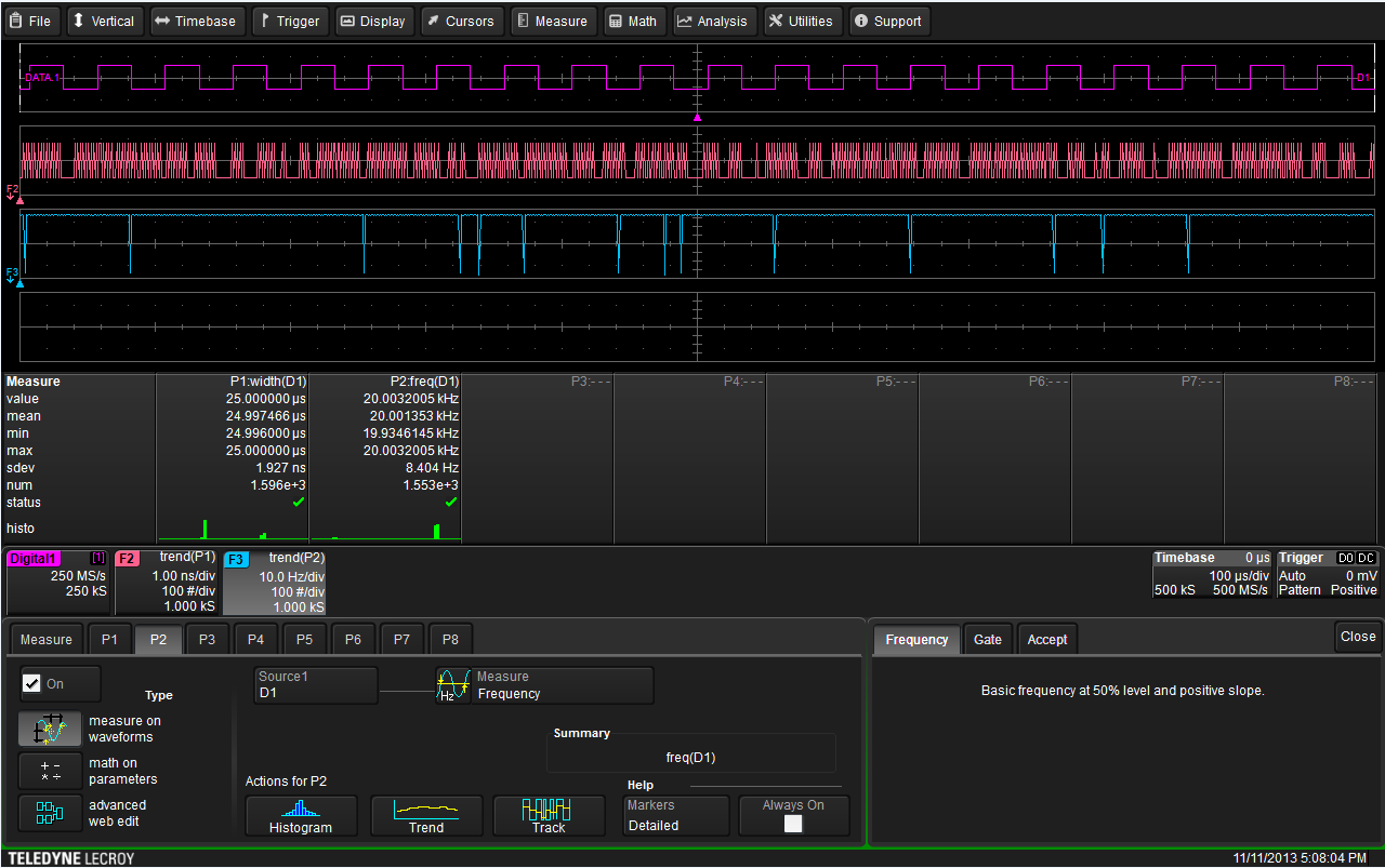
Figure 3:
A full screen capture shows the acquired digital clock signal (D1), the trend plot of pulse width (F2), statistics and histograms, and the channel, timebase, and trigger
Conclusion
Teledyne LeCroy’s HDO4000 Mixed Signal High Definition Oscilloscopes provide powerful tools for measurement and analysis of digital signals. All of these powerful tools make debugging of digital designs quick and painless.