- Eye Doctor II provides the channel emulation and de-embedding tools that engineers need for the next generation of serial data standards
- Adds precision to signal integrity measurements
- Vital for anyone using an 8 GHz or higher oscilloscope
- Seamlessly integrates into Teledyne LeCroy's SDA II software for eye diagram and jitter analysis
- Creates eye diagrams 50x faster than existing solutions
- Uses industry standard Touchstone format S-parameter files for fixture and channel definition.
- Ability to read single ended or mixed mode S-parameter files
- DFE, FFE and CTLE Receiver Equalization
- Fully integrated into the user interface which allows the engineer to use additional Teledyne LeCroy tools for post-processing
- Use Eye Doctor II’s Advanced mode to:
- Flexibly arrange components to allow any combination of de-embedding or emulation for Virtual Probing™ of any point in the test circuit not otherwise accessible
- Increase measurement accuracy through the use of a more advanced transmitter and receiver termination model that incorporates customerspecific characteristics
|
Tools for Next Generation Serial Data Standards
As signal speeds and data rates have increased to 5 Gb/s and greater while propagation mediums have remained unchanged, engineers have had to face new challenges with signal integrity. These faster signal speeds give rise to increased attenuation in the frequencies of interest. These effects were small enough to ignore at lower bit rates, but as rise times get faster and serial data rates increase, these effects must be accounted to avoid unacceptable intrusion into the design margin or completely unusable measurement results. As data rates increase, losses due to the serial data channels and fixtures increase at high frequency leading to eye closures. To truly understand jitter in the serial data signal, these effects must be removed. Clearly, design engineers need new tools to remove the impact of test fixtures and cables, model the impact of serial data channels and fixtures, and simulate the receiver equalization. These capabilities greatly enhance the ability to make useful measurements in high-speed circuits. Additionally, newer serial data standards are requiring such tools in order to make compliance measurements. For example, PCI Express 3.0 will require the use of fixture de-embedding to refer the compliance measurement back to the pins of the transmitter; SuperSpeed USB requires the use of continuous time linear equalization being applied in the oscilloscope software, SATA 6 Gb/s and 6 Gb/s SAS require the emulation of the Transmitter Compliance Transfer Function (TCTF) to simulate the worst allow case channel for debugging compliance failures.
Emulating Serial Data Link Components
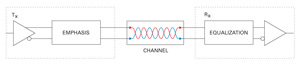
When performing serial data measurements on the physical layer, the main goal is to properly characterize the robustness of the serial data link. Measurements can either be made at the transmitter or the receiver as shown below.
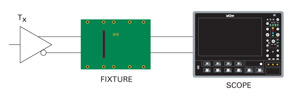
De-embedding Fixture from Tx Measurements
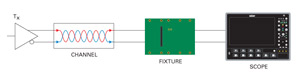
De-embedding Fixture from Rx Measurements
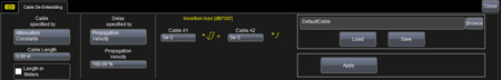
Cable De-embedding
Cable de-embedding is a standard feature on all SDA Zi oscilloscopes and is included with Eye Doctor II. Cable de-embedding gives the user the ability to quickly and easily remove the effect of cables by entering in an attenuation table or attenuation constants that are typically provided by the cable manufacturer.
Adding/Removing Pre- or De-emphasis
Serial data channels have a significant impact on the high frequency content of the serial data signal. Therefore, transmitter designers sometime employ the use of emphasis to pre-compensate for these effects. Eye Doctor II can remove de-emphasis or pre-emphasis from a signal measured at the transmitter output. This is useful when attempting to measure the jitter on such a signal in order to remove the DDj introduced by the de-emphasis. Additionally, Eye Doctor II can add de-emphasis or pre-emphasis to identify the amount necessary to compensate for specific serial data channels.
Cable/Fixture/Serial Data Channel De-embedding
In many typical high frequency measurement situations, engineers desire to connect as directly to their signal as possible and avoid the use of probes. However, even high quality test fixtures, channels, and cables have a negative impact on signal quality that increases with higher signal frequency. While these effects could be ignored at lower frequencies, they should always be accounted for as bit rates increase above 5 Gb/s. If the test fixture, channel, or cable can be electrically quantified in terms of S-parameters using Vector Network Analyzers (VNAs), or Time Domain Reflectometer/Time Domain Transmission (TDR/TDT), then the electrical impact of them can be removed from the measurement result. The result is a measurement that is unaltered by the test setup, and the ability to further measure, apply math, or post-process this true measurement using additional built-in oscilloscope tools, such as parameters, math functions, jitter tracks, histograms, eye diagrams, etc.
Serial Data Channel Response Emulation
Most commonly, a design engineer will perform their serial data measurement at the output of the transmitter. However, the engineer may also be interested in referring their measurement to the far side of a particular serial data channel. To accomplish this they could either use a physical channel and make their measurement after the channel or they can use channel emulation to see what their serial data signal would look like if it had been transmitted through the channel. For example, SuperSpeed USB requires compliance testing through 3 different channels. Having the ability to emulate each of these 3 channels will be very useful to the engineer.
Receiver Equalization
Finally, the serial data receiver often incorporates equalization to compensate for losses associated with the serial data channel. Losses from the channel can cause the eye to be completely closed at the input of the receiver. Even though a receiver that utilizes equalization would be able to properly decode this signal, the oscilloscope jitter analysis software will not be able to recover a clock from the signal and will not be able to perform any jitter analysis. For this reason, the engineer needs the capability in the oscilloscope to emulate the different equalizers their receiver could be using. This would provide him the ability to view the eye diagram and jitter performance on the signal as it is actually seen by his receiver.