Key Features
- Compliant with the Card Electro-mechanical Specification Rev 1.1 and 2.0
- Support for system and add-in card testing
- Integrated SigTest libraries into the oscilloscope software enables automation of the exact algorithms used for compliance testing
- Connection diagrams display proper setup using the PCI-SIG Compliance Base Boards and Compliance Load Boards.
- Report generation incorporates CEM test assertions for 2.5Gb/s, 5.0Gb/s with 3.5dB of de-emphasis and 5.0Gb/s with 6.0 dB of de-emphasis
- Simple and easy-to-use automated testing
The Teledyne LeCroy QPHY-PCIe Test Solution provides automated control for Teledyne LeCroy oscilloscopes for performing the entire transmitter physical layer tests as described by the Card Electro-mechanical specification Rev 1.1 and 2.0
Testing requirements for both system boards and add-in cards are described by the specification. QPHY-PCIe has the ability to test compliance in accordance with the specification for both system boards and add-in cards.
By integrating the SigTest libraries into the oscilloscope software, QPHY-PCIe can fully automate all of the required compliance tests using the exact same algorithms that are described by the specification.
Additionally, QPHY-PCIe can run all of the 2.5GT/s tests, then all of the 5.0GT/s with 3.5dB of de-emphasis test, and finally all of the 5.0Gt/s with 6.0dB of de-emphasis tests. This allows the user to create one test report for all 3 testing phases.
These capabilities make QPHY-PCIe an all-inclusive automated test suite that meets the requirements for 2.5GT/s and 5.0GT/s PCI Express transmitter compliance testing.

Integrated SigTest Libraries
By integrating the SigTest libraries into the oscilloscope software, the exact algorithms provided by the PCI-SIG are used for calculating the results. This ensure the same exact answer as running the stand alone SigTest utility with the added benefit of being able to run this utility from within the oscilloscope software.
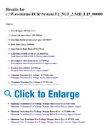
Comprehensive and Easy-to-read Test Reports
Measurement results often need to be summarized and tabulated to quickly verify specifications. This information, together with instrument and signal acquisition/test condition setups, results in a fully documented record. QPHY-PCIe streamlines this process by incorporating an automatic HTML report generation engine. The created test reports contain tabulated numerical values for each individual test result, including PASS/FAIL and specification limit columns. Reports can also be saved as PDF, HTML or XML.
Advanced Debug Capability
If a compliance failure is found, Teledyne LeCroy's SDA II serial data analysis package is available to help find the root cause quickly and easily. SDA II has the ability to perform Eye and Jitter measurements simultaneously and is fully integrated into the oscilloscope application software. In addition, with specialized features such as IsoBER, ISI Plot, Pj Inverse FFT and multiple jitter models, SDA II provides insight into the measured Eye and Jitter parameters making it easier to identify the sources of problems.
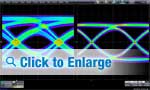
The Eye Doctor II analysis software allows the user to view their signal after Continuous Time Linear Equalization (CTLE), Feed Forward Equalization (FFE) and/or Decision Feedback Equalization (DFE). This gives the user to ability to see how an actual receiver that utilizes equalization would interpret their signal.
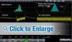
Teledyne LeCroy's SDA II analysis software contains integrated jitter and timing analysis for clock and data signals. It allows analysis of data up to the memory limit of the oscilloscope and using X-Stream II technology, SDA II can display eye diagrams and jitter decomposition results up to 50 times faster than other solutions. Additionally, the specific PLL for PCI Express is selectable from a list of pre-configured PLLs. Lastly, SDA II contains 2 separate methods for jitter decomposition; the industry standard spectral method, and the NQ-scale methods. NQ-scale is critical for properly distinguishing between random and deterministic jitter in systems where cross-talk is present.
Additionally, the Eye Doctor II analysis software also enables channel emulation. For PCIe testing, a design engineer will perform their serial data measurement at the output of the transmitter. However, analysis at the far side of a reference serial data channel is very useful for debugging problems.. To accomplish this they could either use a physical channel to make their measurement after the channel or they can use channel emulation to see what their serial data signal would look like if it had been transmitted through the channel.