A useful debugging tool is logic-gate emulation, which allows users to simulate and debug complete digital designs. The Mixed Signal High Definition Oscilloscopes enable accomplishing this task within the instrument itself. Combined with the powerful Processor Web Editor utility, many logic gates may be daisy-chained together to create complex digital designs.
For purposes of this demonstration, digital lines D0-D4 of the 16-channel digital lead set were connected to clock pins of varying speeds. Next, press the Dig (for Digital) button in the Vertical section of the front panel. This will activate the digital channels.
Logic gate emulation is accessed through the oscilloscope’s Math menu. Select the Math pull-down menu and choose F1 Setup (Figure 1).

The F1 setup dialog box
Press the Operator1 button. In the Select Math Operator dialog box, specify the category as Digital. Under choices, select DigitalAND (Figure 2).
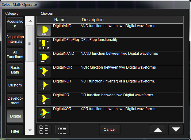
The Select Math Operator dialog box
Press the Source 1 button. In the Select Source dialog box, select Digital Lines as the category and set Source1 to D0. Similarly, set Source2 as D1.
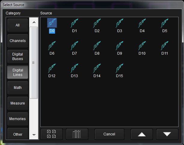
The Select Source dialog box
Turn the F1 trace on to confirm that the result is the logical AND of the D0 and D1 signals (Figure 4).
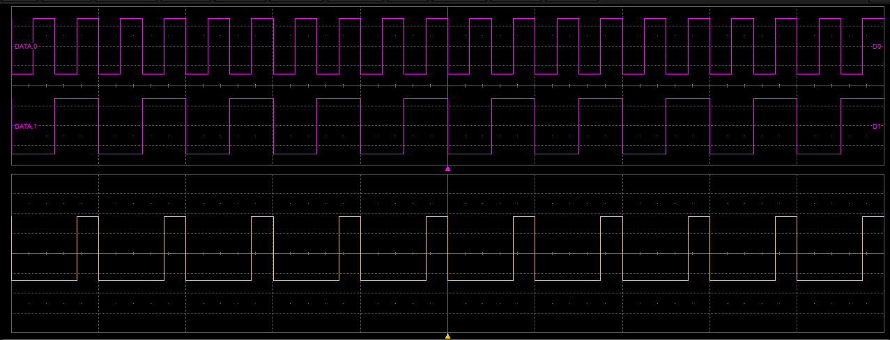
The magenta traces are digital lines D0 and D1; the yellow trace is that of the digitalAND operation that combines them in emulation
Using logic gate emulation in combination with the Processing Web Editor allows combining many digital gates together in one math function to emulate complex designs (Figure 5). AND, OR, NAND, NOR, XOR, NOT and D Flip Flop gates are all available as math operators to enable debugging complete digital systems. The Processing Web Editor enables a graphical approach to problem solving by allowing users to develop math and measurement processing chains in a familiar block diagram/flowchart format.
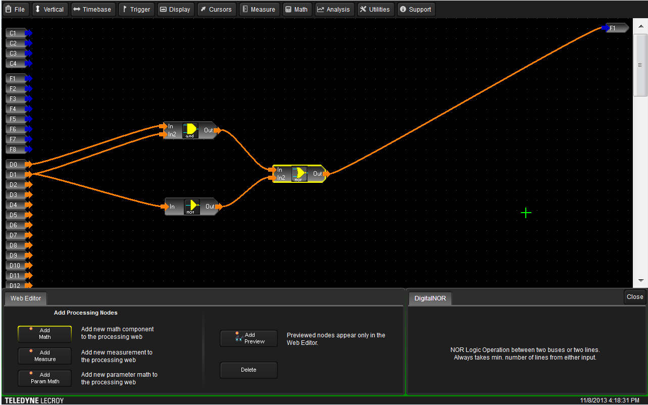
The Web Editor function enables users to combine many digital gates in a single complex math function to emulate complex designs
The Processing Web Editor is accessed by touching the Math drop-down menu, followed by Math Setup. Next, open the F1 tab and press the web edit button on the left side. Check the Trace On check box. Press the Show Processing Web button to open the Processing Web Editor.
Within the Web Editor are buttons for adding math, measurements, and parameter math functions (Figure 5, again). Another button labeled Add Preview opens viewing windows that show the waveform or measured value at the output of any operation.
The Math tab in the Web Editor dialog enables users to set the function of any math traces to single operator, dual operator, historgram, or web edit (Figure 6). By default, F1 is set as the output from the processing web, which is indicated by the F1 terminal on the right side of the Web Editor.
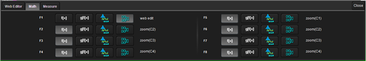
The Math tab within the Processing Web Editor dialog enables users to set the function of math traces.
The Measure tab in the Web Editor allows users to set the function of any of the measurement parameters to be a simple measurement, parameter math, or the Web Editor (Figure 7).
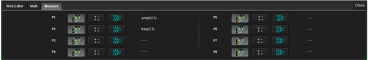
The Measure tab allows users to set the function of any measurement parameters
Touching the Add Math (or Add Measure, or Add Param Math) button opens the Add Math Processor, which allows selection from a large range of basic math functions, custom functions, filters, frequency analysis, and more (Figure 8).

The Add Math Processor dialog box
Once math components, measurements, and/or parameter math functions have been added to the Web Editor grid, simply touch and drag them into position. Then, interconnect them to channel inputs/outputs and to each other in the desired configurations by drawing interconnect lines with a fingertip or the stylus.
Teledyne LeCroy’s Mixed Signal High Definition Oscilloscopes offer digital input channels, which combined with the Processing Web Editor utility, comprise a powerful debugging tool enabling users to emulate logic gate designs in a large range of configurations.