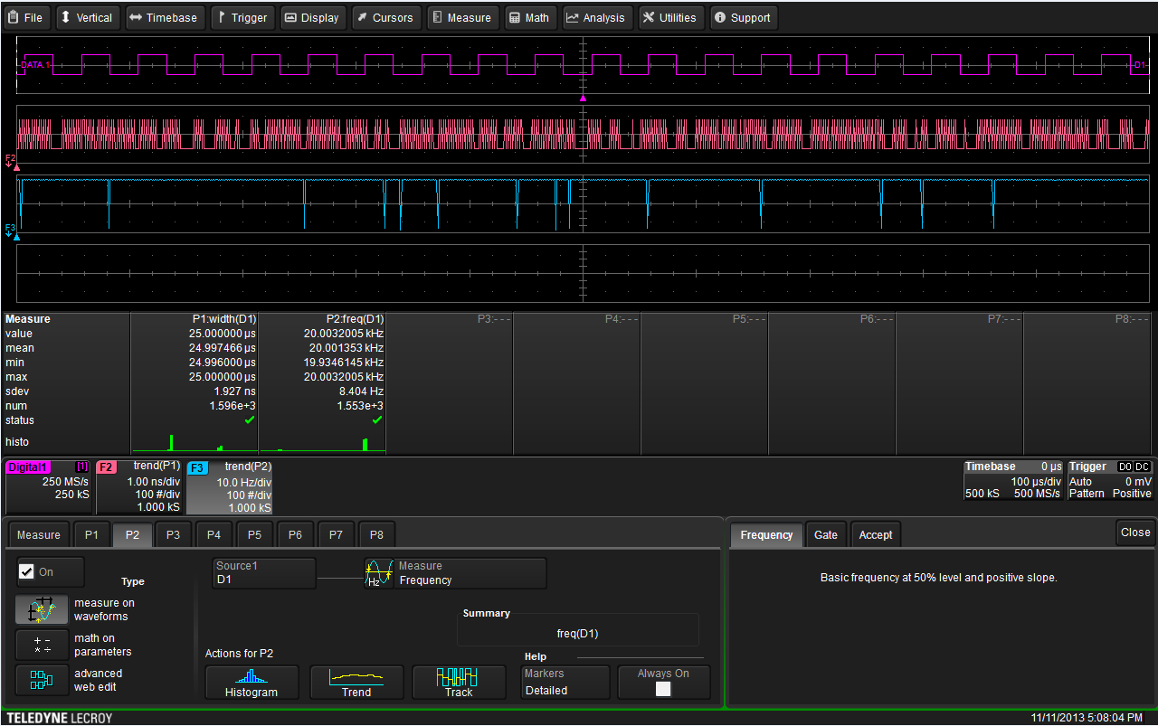
The combination of Teledyne LeCroy’s Mixed Signal High Definition Oscilloscopes and their 16 digital signal inputs with the instruments’ WaveScan technology makes it a simple matter to identify matching patterns across many digital lines. Identified patterns are presented in a table with timestamp information and enable quick searching for each pattern occurrence. Here, we will examine an example of how to set up such a debugging scenario.
For purposes of this demonstration, digital lines D0-D4 of the 16-channel digital lead set were connected to clock pins of varying speeds. Next, press the Dig (for Digital) button in the Vertical section of the front panel. This will activate the digital channels (Figure 1).
The Digital Channels dialog box, where users may indicate how many, and which, of 16 available digital input lines are to be shown on the display
WaveScan may be enabled by either accessing it through the Analysis pull-down menu on the touch screen or by simply pressing the WaveScan button on the front panel. Next, check the Enable box in the WaveScan dialog (Figure 2).
The WaveScan dialog box
Now set the WaveScan mode to Bus Pattern. Touch the Source1 button and select Digital Buses under Category. Under Source, select the group of digital lines of interest. The Digital Channels dialog contains four tabs for groups Digital1 through Digital4.
At the right side of the WaveScan dialog box is a tab labeled Pattern Time. There, users may select either Binary or Hex viewing modes, specify the pattern for search, and indicate how many instances of the pattern WaveScan should report (Figure 3).
The Binary Virtual Keypad, found in the WaveScan dialog, enables users to specify the binary or hex pattern to be searched for in the acquired waveform(s)
Next, select an action for WaveScan to perform upon discovery of the specified pattern. This is found in the WaveScan dialog under Action on Features Found. For our example, we will have WaveScan stop acquisition. Other options include saving the waveform(s), saving as a LabNotebook documentation and report generation entry, setup of a pulse AUX output, printing the screen to a file or hard copy, or simply emitting a beep (Figure 4).
Shown are the various actions WaveScan may be set to take upon discovery of the specified bit pattern
In this instance, we have indicated that WaveScan is to report 10 instances of the specified pattern. These are seen in a table at the upper left corner of the display. Enable the table by checking the Table box in the WaveScan dialog. Note that WaveScan will have stopped the trigger. Touching any entry in the table automatically zooms to that instance in the acquired waveform (Figure 5).
In this full screen capture, note the WaveScan table at upper left with instance 7 of 10 of the specified bit pattern highlighted. The zoom trace automatically displays the highlighted instance
Teledyne LeCroy’s Mixed Signal High Definition Oscilloscopes provide powerful tools for measurement and analysis of digital signals. All of these powerful tools, such as parallel pattern search using WaveScan, make debugging of digital designs quick and painless.