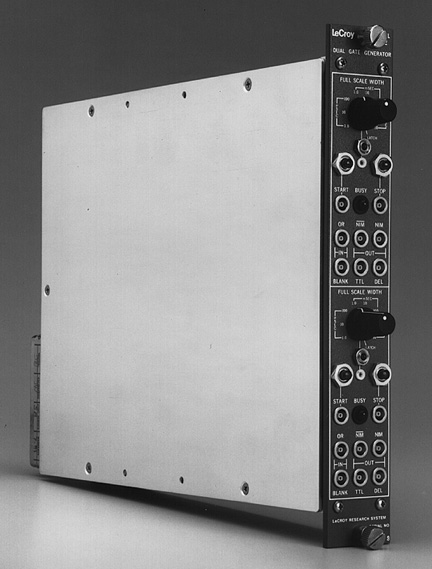
222 NIM Dual Gate and Delay Generator |
|
The Model 222 Dual Gate and Delay Generator provides two complete delay/gate channels
in a single NIM module. The 222 eliminates the common problems exhibited by other gate
generators. There is negligible recovery time associated with the unit at any width
setting; it may be retriggered immediately after the gate returns to its quiescent state
in all ranges. Each channel of this single module can also be used to provide delays and
gate outputs and to drive bin gates in its own NIM bin (LeCroy Model 1403) and several
external bins. In addition, an OR input for each channel permits the gate and delay
interval to be extended by an external input.
The 222 provides a range switch and a screwdriver-adjustable potentiometer to permit
continuous adjustment of gate durations from less than 100 nsec to greater than 11
seconds. A front-panel LED remains on when gate output is present, even if extended by the
OR input. The approximate gate setting may be easily determined without an oscilloscope by
means of the front-panel monitor point, which provides a DC voltage related to the gate
duration. A conversion graph is enclosed with the unit. In addition to preset width
ranges, the range switch has a "Latch" position to provide a continuous gate
controllable by either the "Start" and "Stop" inputs or by the
"Start" and "Stop" push-buttons. The push-buttons permit manual
operation when the full scale switch is set on "latch", and single-shot
presettable operation when the full scale switch is in any other position.
INPUT
START Input: One; responds to both fast NIM-level and TTL-level inputs.
Fast NIM Input Requirements: Greater than -600 mV enables; minimum width 5 nsec; 50
ohm impedance for any input from +100 mV to -5.0 V.
TTL Input Requirements: Greater than +2.5 V enables; minimum width approximately 20
nsec; high impedance for any input from +400 mV to +6 V. (Requires +5 mA at +2.5 V.)
STOP Input: One; characteristics same as for "Start" input. Used when
range switch is in Latch position. Can be used in Preset position but will cause a
"delayed stop".
Blanking Input: One; requires fast NIM-level inputs ( -600 mV) 50 ohm impedance;
blanks all outputs which occur during its presence, including the delayed output*. Maximum
blanking rate, 80 MHz.
"OR" Input: One; requires fast NIM-level inputs ( -600 mV) 50 ohm
impedance; extends preset gate duration by the portion of its input signal that occurs
after the preset output time.
OUTPUT
Gate Outputs: One standard fast NIM-level output (quiescently 0 V; -750 mV during
pulse) of approximately 2 nsec rise time; fall time slightly longer on wide widths. One
complementary fast NIM-level output (quiescently -750 mV; 0 V into 50 ohm during pulse).
One TTL-level output (quiescently 0 V; > +2.5 V into 50 ohm during pulse).
Delayed Output*: Delivers 10 nsec (FWHM) fast NIM-level signal into 50 W. Occurs
approximately at the trailing edge of the preset or start-stop gate output (including any
gate extension due to input "OR"); 2.5 nsec rise time.
Presettable Gate Durations: Continuous from < 100 nsec to > 11 sec plus
latched position; full scale switch determines range. Screwdriver adjustment vernier
permits fine adjustment from 10% to > 110% of full scale. Front-panel test point gives
DC voltage related to gate width (in % of range switch setting). Conversion chart included
with module. Output width jitter, approximately 0.05% of setting.
GENERAL
Recovery Time: None; unit may be retriggered immediately after gate output returns to
its quiescent state.
Input-Output Delay: 14 nsec.
Manual: Front panel "Start" and "Stop" push-buttons permit
manual operation when full scale switch set on "latch", and single-shot
presettable operation when full scale switch is in any other position.
Bin Gate Driver: Each channel has one rear panel Lemo-type connector which switch
selectively drives external bins in either normal or inverted direction. Logic 1: < 1 V
at 200 mA; Logic 0: 0.5 V into high impedance (2 kohm).
Channel Select Switch: Rear panel 3-position switch (A/B/Off) determines which
channel drives the bin in which the Model 222 is located.
Busy Indicator: Front panel LED remains on when gate output is present, even if
extended by "OR" input.
Packaging: NIM-standard single width module; Lemo-type connectors.
Current Requirements: 95 mA at +12 V, 180 mA at -12 V, 45 mA at +24 V, 80 mA at -24
V, 235 mA at +6 V (drawn from +12 V if unavailable).
*Blanking of the delayed output may be disabled by factory option.
DUAL GATE GENERATOR TIMING DIAGRAMS
Presettable Width Mode Diagram
Latch Mode Diagram
Copyright� September 1995. LeCroy is a registered trademark of LeCroy Corporation. All
rights reserved. Information in this publicaction supersedes all earlier versions.