2366 Universal Logic Module |
|
- 59-Bit Input Register;
- 59-Bit Output Register;
- CAMAC Dataway Tester;
- 100 nsec LSB 24-Bit TDC;
- 2 Channel Latching Scaler with FERA Readout
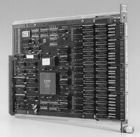
The CAMAC Model 2366 is a general purpose programmable logic module, using state-of-the-art field program mable gate array technology. This CAMAC module can be used as a programmable LeCroy ECLine trigger processor module. In addition to a full 24-bit CAMAC interface, there are 59 front panel differential ECL I/O signals, which (with some restrictions) can be independently selected to be either inputs or outputs. This module is also useful as a general purpose controller, as part of a test system or data acquisition system.
Application possibilities of the 2366 are endless. All common logic functions such as ANDs, ORs and flip-flops can be programmed in any combination, to perform complex logic functions such as counters and multiplicity logic. These possibilities make the 2366 virtually indispensable for high energy or nuclear physics experiments.
The desired logical operations of the Model 2366 are programmed in a Xilinx 4005 gate array chip. Any logic that can be implemented as a synchronous (clocked) state machine may be programmed, subject only to the limitations of the Xilinx gate array chip (approximately 5000 equivalent gates). There are 3 clocks available on the board, 40, 20 and 10 MHz, or any of 3 special front panel inputs may be used as a clock. Input and output signals use standard 10124 and 10125 TTL-ECL level translators. Input signals as short as 5 nsec can be latched and synchronized with the internal state machine logic.
The gate array must be programmed after power-up, and can be reprogrammed at any time. An on-board EPROM contains a program which is loaded on power-up, or reloaded on CAMAC command (F30 followed by F25). The Xilinx chip may also be programmed directly from the CAMAC dataway. The program information is stored in RAM in the Xilinx chip, so there is no limit to the number of times that it can be reprogrammed. Please note that the XACT program from Xilinx is required to use this module to its full potential. XACT runs on PCs or SUN workstations and is available directly from Xilinx.
The initial program in the EPROM is T2366E. This implements a simple divide chain to
flash the LEDs with the 3 internal clocks (40 MHz, 20 MHz, and 10 MHz), a 24-bit read
write register and a register which latches the CAMAC F, A, Z, I, N on every S2. This last
register is read by F0, A1. This emulates most of the test portion of the LeCroy 2050
CAMAC dataway display and test module.
A simple basic program which exercises the 2366 is EPRM2366.bas. It starts by forcing the
reload of the Xilinx chip from the EPROM (with T2366E), and implements a simple CAMAC
system test.
Two bit files are available for operating the 2366 as either a 59-bit input or output register. Please contact LeCroy for more details on CAMAC operation.
The 2366 has been configured to operate as a single-channel, multi-start multi-stop,
multi-hit TDC with 100 nsec LSB, 1.6 sec full scale. Up to 31 hits can be digitized within
the full scale time range. For more details, please call LeCroy.
The example program LOAD2366.bas will load an arbitrary xxxx.bit file into the Xilinx
chip. This is produced by the Xilinx software Makebits program (Xilinx, 2100 Logic Drive,
San Jose, CA 95124).
A novel application is a multichannel scaler with FERA-style front-panel readout
functionality. In this configuration, the 2366 has 2 input scalers with 32-bit range. Data
can be read out via CAMAC, or through a front-panel ECLbus into a buffer memory (Models
4302 or 1190). Readout is compatible with other LeCroy FERAbus modules, Models 4300B and
3377.
Programmable Gate Array: Xilinx 4005 approximately 5000 gates; 196 configurable
logic blocks, 616 flip-flops; 112 I/O blocks; 6272 Ram bits; fast carry logic; wide
decoding.
Crystal Clocks: 40, 20 and 10 MHz.
Programmed: By optional on-board (socketed) EPROM on power up, or by CAMAC command
to reload from EPROM.
Programmable via CAMAC: Any time, independent of EPROM. Xilinx XACT software system
is required for programming. Uses Xilinx .BIT file for programming. Software for IBM
compatible included; 11,875 CAMAC F16 write operations are required to program. All logic
must be clocked (synchronous logic).
CAMAC Interface: Programming, 8-bit write only interface. Test for successful
programming. After programming all CAMAC control and data lines (N, F, A, 24R/W, C, Z, S1,
S2, Q, X, L) are available to Xilinx chip. Only 1 function code is reserved for
reprogramming, all others are available for the user.
CAMAC Interface Pin Assignments for Xilinx 4005-PGA156
Enables for Bidirectional 24-Bit CAMAC-Write Bus:
| Re* | T11 | Read Enable | R1-R24 |
| Wr1* | R11 | Write Enable1 | W1-W8 |
| Wr2* | A8 | Write Enable2 | W9-W24 |
Direction for R1-R24, normally +5 V, pin T1.
The 3 Internal Clock Sources:
10 MHz - T15
20 MHz - B16
40 MHz - B3
FRONT PANEL PIN ASSIGNMENTS
3 Programmable LEDs: Red = N, lights when module is accessed. Yellow, green =
programmable from gate array chip.
Top = D14 (green), bottom = C16 (yellow).
Front Panel Input-Output Pins
All inputs and outputs are differential ECL. Inputs are terminated for 120 W
twisted-pair cable.
All I/O is selectable as input or output in groups of 4, as indicated by the grouping in
the preceding table (the 3 clock inputs are separately selectable). This is accomplished
by selectively loading the socketed ECL-TTL level converters and the appropriate
termination resistor networks.
The corresponding Xilinx pins must be programmed as either input or output.
For input only, the 10125s, ECL-to-TTL converters, and the 56 W termination resistor SIPs
are installed. The inputs are properly terminated for twisted-pair cable.
For output, only the 10124s, TTL-to-ECL converters, and the 390 W pull-down resistor SIPs
are installed.
The logical polarity of any signal is programmable. There are a total of 59 I/O signals.
The 17th pair on connector B, C & D can be connected to secondary clock nets inside
the Xilinx chip, or can be used as ordinary I/O, individually selectable as input or
output.
For bidirectional TTL I/O, both the 10124 and the 10125 are removed, and a special DIP
jumper with series resistors is installed. This connects the Xilinx pin directly to the
front panel connector with only a series resistor for protection. Note that the Xilinx pin
will not drive a terminated cable. For long cable lengths (more than 1 meter), or fast
signals, the ECL drivers must be used.
GENERAL
Packaging: CAMAC #1 Module
Power Requirements: 1.0 A at +6 V; 0.9 A at -6 V.
CAMAC FUNCTION CODES
F(9)·A(0-15): Disable PAL except for F30 (CAMAC C, Z has same effect).
F(12)·A(0-15): Test Xilinx READY line (normally not required).
F(13)·A(0-15): Test Xilinx program DONE.
F(14)·A(0-15): Test Xilinx INIT line.
F(16)·A(0-15): Write 8 bits to the Xilinx.
F(25)·A(0-15): Program Xilinx chip (program pulse lasts until the next S1).
F(28)·A(0-15): Select CAMAC programming mode.
F(30)·A(0-15): Enter programming mode with EPROM selected. Enable all other PLD
function codes.
This module has been used as a drift chamber trigger using the trigger outputs of the 2277 CAMAC TDC. The one shots needed to stretch the signals, the pattern logic and trigger delays required to produce the Common Stop pulse, the busy outputs, etc., are all easily accommodated in a single CAMAC module. Any trigger or control requirement that can be expressed as a clocked state machine can be programmed in the module. A few examples are:
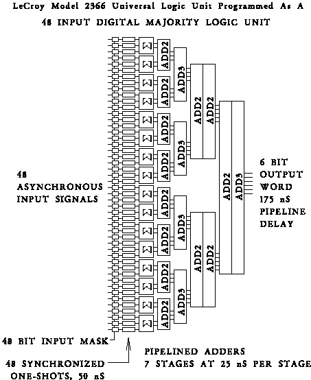
As a concrete example, we have programmed the 2366 to be a 48-input digital majority logic
unit. This unit counts the inputs and delivers the binary results every 25 nsec, with a
175 nsec pipeline delay. A 48-bit mask register (written from CAMAC) enables or disables
each of the 48 inputs. See the schematic shown. Application
Note AN-52, describing this Xilinx program in more detail, is available upon request.
Copyright© October 1997. LeCroy is a registered trademark of LeCroy Corporation.
All rights reserved. Information in this publicaction supersedes all earlier