3377 DRIFT CHAMBER TIME-TO-DIGITAL
CONVERTER
|
|
- 500 picoseconds LSB
- Programmable Full Scale Time Range, 8 nsec to 32 µsec in 8 nsec Steps
- 32 Channels Per CAMAC Module
- Up to 16 Measurements (Hits)/Channel (Programmable)
- Multi-Event Buffering
- Rising and/or Falling Edge, Allows Pulse Width Measurements
- Compatible with LeCroy FERA Systems
- Fast Conversion, 1.8 µsec + 100 nsec/Hit
- Programmable Trigger Outputs
TDC FOR HIGH-RESOLUTION TIME MEASUREMENTS
The Model 3377 is a 32-channel, CAMAC-based time-to-digital converter (TDC) designed
for drift chamber applications which require low measurement dead times. The 3377 has been
optimized with a low conversion time and a high speed ECL data port for fast readout.
The 3377 offers several significant features not found in previous drift chamber systems.
Major benefits include: multihit capability which allows pulse width measurements, up to a
16-bit dynamic range (full scale) with 500 psec LSB, all digital design, low dead time and
compatibility with the LeCroy FERA System and with other modules using LeCroy ECL bus.
The 3377 is the perfect upgrade choice for LeCroy 4290 System users. It has high data
throughput rate of 100 nsec/word, without using a dedicated crate and it has multihit
capability. The front panel hit input layout is compat ible with the existing 4291 system,
thus simplifying replacement.
FUNCTIONAL DESCRIPTION
The Model 3377 TDC is a CAMAC instrument used to make low dead time measurements of
multiple time intervals, accurate to 500 psec for time ranges up to 32 µsec.
The times are measured with respect to a common reference time mark or "COMMON
HIT", which can occur before or after the individual time signal (also called
"HIT") inputs to be measured. This common reference concept is appropriate when
the relative times between one input channel and any other input channel is of interest,
since they are both measured with respect to a common time. It is also appropriate for
absolute time measurements between the individual signal inputs and the reference itself.
Because many experiments need to make a large number of time measurements, the 3377 has
incorporated 32 independent signal channels. In addition, each individual input channel
has a LIFO type buffer attached to it such that up to 16 hits can be recorded on the
channel with respect to the common hit.
The 3377 inputs are an edge sensitive design. Consequently the polarity of the logic
signal inputs is selectable. The module will record the time of the rising, falling, or
both signal edges.
The 3377 may be read out over CAMAC or via the ECL port. The ECL port offers high speed
(100 nsec/word) data transfer to buffer memories such as CAMAC 4302 and VME 1190. It can
be used as a stand-alone module or part of the LeCroy FERA system. Common signals can be
passed up to 22 modules via the LeCroy 4301 driver module. The 4301 also provides
differential ECL output when multiple 3377 ECL ports are connected.
Common Start and Common Stop Modes
When the common reference time precedes the signal times, the 3377 is operating in a
"COMMON START" mode. Alternatively, if the inputs precede the reference the
"COMMON STOP" mode is used. Of course, by adding delays to the common or
individual signals either mode can be used.
Common start mode is typically preferred in synchronous situations, such as colliding beam
accelerators or pulsed laser experiments, when the time interval to be measured can be
associated in time with a causal effect. In common start mode, a time window for the
measurements must also be provided to terminate the measuring process. This can be
internally generated in the 3377 or supplied from an external source via a front-panel
input.
Common stop mode is better suited to continuous beam or randomly occurring events when a
trigger decision is required. The 3377 Common Stop range (full scale) can be programmed to
eliminate data "older" than the range of interest.
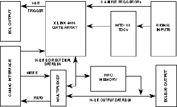
Model 3377 Block Diagram
Configuration Options
The 3377 has several features and modes of operation which are selected and configured
from CAMAC. They include the following:
1. Full scale time range programmable from 8 nsec to 32 µsec in 8 nsec steps.
2. Maximum number of hits recorded per channel, programmable from 1 to 16.
3. Rising edge only or rising and falling edge recording.
4. ECL port readout or CAMAC readout.
5. Multievent Buffering - at least 4 full events may be buffered. Variable size event
buffers. Maximum number of small events is 31.
6. FERA 4300B compatibility mode allows mixing 4300B and 3377 modules in the same ECL port
bus.
7. Common Stop mode.
8. Common Start mode. The time out is programmable up to 32 µsec in 50 nsec steps.
9. MPI (Measure Pause Interval), programmable to 0, 0.8, 1.6 or 3.2 µsec. An external
input is provided to extend the MPI.
10. Single word readout
a) LSB programmable to 0.5, 1, 2 or 4 nsec
b) Programmable offset from 0 to 32 µsec in 8 nsec steps. Data values less than the
offset are discarded.
c) For rising edge only mode, 10 bits (0-1023) of data are read out, for rising and
falling edge, only 9 bits (0-511) are read out.
Note, the LSB, the offset and the maximum time range must be set in a consistent and
compatible way.
11. Double word readout
a) The full 16 bit range is available
b) The LSB is fixed at 500 psec
12. Test modes to verify operation of TDCs and integrity of the data paths.
The data can be read through CAMAC or via the ECL port. The header and data formats are
the same for both CAMAC and the ECL port. The readout is complete when F0 returns Q = 0,
or when the PASS output is gener ated. The ECL port readout can be accomplished at 10 MHz
rates and when combined with the derandomizing feature of the buffer memory, provides one
of the fastest data movers available today. A simple token/pass readout control via
"REN" and "PASS" connections provides a means of continuous readout of
buffered events with no external control. This is simply done by connecting the
"PASS" of one module to the "REN" of the next module. The
"PASS" of the last module is inverted (180° twist of the ECL 2-pin cable) and
connected to the "REN" of the first module. Other necessary interconnections and
signal connects are provided by the Model 4301 System Driver.
The 3377 has several programmable readout modes. In the double word mode, two words are
read out for each hit, via the CAMAC backplane or the front panel ECL bus. In this mode,
all 16 bits of time measurement are preserved.
The single word mode is available for those experiments which require the fastest readout
rate and which do not need all 16 data bits. By simply programming a control register,
either 9 bits of data with leading and trailing edge indicators or 10 data bits of leading
edge times only are read out. The higher order values are not read out (truncated) with
this option. A further choice of the time range of the data is made by selecting a data
shift value. The data can be shifted by up to 3 bits, effectively changing the LSB from
500 psec to either 1, 2 or 4 nsec. The maximum time range varies accordingly, from 512
nsec for 500 psec LSB and 9 bits (rising and falling edges) to 4096 nsec for 4 nsec and 10
bits (rising edge only).
A programmable offset register provides a time window capability. The offset value is
subtracted from the data before shifting. The result of the subtraction, appropriately
shifted is the output data. Data words less than zero are discarded.
The various readout options and the two readout ports make the 3377 a very flexible unit
which can fulfill the requirements of almost any experiment.
Test Features
The 3377 contains an internal pulse generator so that signals can be injected to verify
the behavior of each channel. This is available in Common Start mode only.
Compatibility
The 3377 was designed to be used with a fast encoding and readout ADC (FERA) system.
Please see the 3377 manual for more details.
The 3377 is very similar to the Model 2277. However, the 3377 has the following
distinctive features: 0.5 nsec LSB; fast ECL port; buffered data; more flexible operation
including programmable readout, time range and number of hits. Note that the output word
format is different and therefore is not directly compatible with the 2277's.
Additional Features and Applications
Prompt hit information is presented at the rear panel TRIG OUT port for inclusion in
first or second level trigger decisions. Each of the 8 ECL outputs is the OR of 4 input
channels. A hit on any of the 4 channels produces an output which is programmable. In
Common Stop mode, the width and pipeline delay are programmable, and the outputs are
latched during MPI. In Common Start mode, hits are latched between Common Start and the
Time Out, and remain latched while the module BUSY is asserted.
By capturing both the rising and falling edge time information, the 3377 can be used in a
time-over-threshold technique to simultaneously determine time and charge from a given
detector element. This low cost technique avoids many of the traditional problems of using
ADCs and TDCs for the same signals.
SPECIFICATIONS
GENERAL
Channels: 32, differential ECL inputs. Impedance 120 ohm. Unused inputs/outputs can
be left open.
Range: 16 bits.
Full Scale: 8 nsec to 32.767 µsec, programmable in steps of 8 nsec.
Least Significant Bit (LSB): 500 psec.
Total R.M.S. Error: < 400 psec maximum; typically, 250 psec (Note: The R.M.S. of
a gaussian distribution is equal to sigma.)
Double Pulse Resolution: < 10 nsec.
Long Term Stability: 25 ppm/year.
Integral Non-Linearity: None (0%).
Differential Non-Linearity: < ±10%.
Fast Clear: 10 nsec minimum width (edge triggered). Recovery time is 200 nsec +
time to synchronize with the internal 10 MHz clock.
Buffering Time: 1.8 µsec + 100 nsec per hit (dead time), in single word mode.
Data Format: Depends on readout option selected; refer to readout word bit pattern.
Mechanical: #1 CAMAC Module according to IEEE-583 Standard.
Weight: 1.5 lbs. (0.7 kg).
Common Start/Stop: Front-panel ECL 2-pin connectors; 120 ohm terminating resistors.
Power Requirements: 2.0 A at -6 V; 1.1 A at +6 V; 0.17 A at -24 V; 0.025 A @ +24
V.
INPUT SIGNALS
IN 0-31: 32 channel inputs; differential ECL signal standard. Terminated with 120
ohm.
OUTPUT SIGNALS
TRIGGER OUT: Eight differential ECL outputs on rear panel. Each output is the OR of
4 input signals. In Common Stop mode, the outputs are stretched and delayed. The width and
delay are programmable in 25 nsec steps. The outputs are latched during MPI. In Common
Start mode, any hits that arrive during the acquisition period (from the Common Start to
time out) are latched and held until the end of MPI.
MODE CONTROL
The 3377 can be made compatible with 4300B FERA modules. In the 4300B mode, the command
bus of the 3377 is compatible with the 4300B/4301 command bus and multievent buffering is
disabled.
COMMAND BUS
Connector: 13 x 2-pin front-panel connector. The input terminations and output
pull-down resistors may be removed for high impedance inputs and outputs.
Input Levels: Differential ECL levels, 120 ohm terminator.
Output Levels: Differential ECL levels.
Common Input (COM): One; common for all TDC channels. Note: This signal is called
Gate on the FERA ADC (4300B) and FERA driver module (4301).
Clear Input (CLR): One; in buffered mode, active only during Measure Pause Interval
(MPI) and clears the current event only. In 4300B mode, clears module of all data and
enables readout for next event.
Busy (BSY): One; In buffered mode, "Busy" is true for busy duration of
the 3377 which is variable and depends on acquisition window, MPI and number of hits. The
busy duration is defined as the time from the common input to when the current event is
either loaded into buffer or cleared by a "Fast Clear". Busy remains true when
the buffer is full. In 4300B mode, Busy becomes the equivalent of Request (REQ) on the
4300B command bus. It is important that the Busy, in this mode, turns "True"
after the leading edge and before the trailing edge of the 4300B OR'd request. Therefore,
an adjustable delay (5 - 30 µsec) is provided between the common input and the leading
edge of request.
Write Strobe Output (WST): One; indicates when the data are valid on the ECL port
output. WST is set within 25 nsec after the data are presented to the ECL port (settling
time) and released when the write acknowledge is received. The ECL port data are stable
during the entire WST pulse. The minimum write strobe width is 50 nsec.
Write Acknowledge Input (WAK): One; acknowledges the signal from the ECL port
receiver indicating that the data have been loaded and that the next data word may be
sent. The next WST is set 50 nsec after the release of WAK. A fast FERA mode is provided,
selected by a bit in a control register, which causes data to be output at 10 MHz. The
WST/WAK handshake is not used. WAK is used only for flow control in this mode.
Time Out Input (T-O): One; allows external control of acquisition time window. OR'd
with CAMAC programmable time window control.
ECL PORT ENABLE/PASS (token/pass)
The behavior at the REN and PASS signals depends on the operating mode selected. Please
see the 3377 manual for details.
Readout Enable Input (REN): 1 x 2-pin front-panel connector. Accepts differential
ECL levels.
Pass Output (PASS): 1 x 2-pin front-panel connector, generates differential ECL
levels (into 120 W differential).
ECL PORT OUTPUT
Connector: 17 x 2-pin front-panel connector; (BERG 75789-101-34). The last 2
pins are not connected.
Output Levels: Differential ECL levels (into 120 W differential). The pull-down
resistors may be removed for high impedance outputs.
Specifications: Data word size: 16 bits. Sequential data readout with maximum
output frequency 10 MHz.
CAMAC COMMANDS
CAMAC Function Codes
F(0)·A(0): Read FIFO data until end of event, Q = 1 for valid data, Q = 0 at
end.
F(0)·A(1): Read FIFO data always (Common Start only).
F(0)·A(2): Examine FIFO output, do not advance FIFO (Common Start only).
F(1)·A(0): Read Control Register 0.
F(1)·A(1): Read Control Register 1.
F(1)·A(2): Read Control Register 2.
F(1)·A(3): Read Control Register 3.
F(1)·A(4): Read Control Register 4 (Common Start only).
F(1)·A(5): Read Control Register 5 (Common Start only).
F(1)·A(6): Read CAMAC Test Register (Common Start only).
F(8)·A(0): Test LAM.
F(9)·A(0): Clear all data and LAM. This does NOT affect the control registers.
F(10)·A(0): Clear LAM.
F(16)·A(0): Write 16-bit data to FIFO (Common Start only).
F(16)·A(1): Write FIFO tag bit (Common Start only).
F(17)·A(0): Write Control Register 0.
F(17)·A(1): Write Control Register 1.
F(17)·A(2): Write Control Register 2.
F(17)·A(3): Write Control Register 3.
F(17)·A(4): Write Control Register 4 (Common Start only).
F(17)·A(5): Write Control Register 5 (Common Start only).
F(24)·A(0): Disable LAM.
F(24)·A(1): Disable Acquisition Mode.
F(25)·A(0): Initiate test cycle (Common Start only).
F(26)·A(0): Enable LAM.
F(26)·A(1): Enable Acquisition Mode.
F(27)·A(0): Test buffering in progress (BIP), Q = 1 while BIP.
F(27)·A(1): Test busy, Q = 1 while busy.
F(27)·A(2): Test event ready, Q = 1 if event ready for readout.
F(27)·A(3): Test FIFO tag bit, Q = 1 if tag bit set for word to be read next.
F(30): Begin the reprogramming sequence.
For completeness, the following commands are available only during the programming mode of
the Model 3377's internal Xilinx logic chip. These enable the mode to be set by selecting
a firmware program from the 4 that are installed in the EPROM, or loading a different
program from CAMAC. For these commands, the A lines are not decoded, they are simply
ignored.
F(9): Clear data buffers, enable Xilinx program.
F(12): Test if Xilinx ready for data (Q = 1 when ready).
F(13): Test Xilinx programming done (Q = 1 when done).
F(14): Test Xilinx INIT signal.
F(16): Write 8 bits to Xilinx.
F(21): Select EPROM Mode 1.
F(22): Select EPROM Mode 2.
F(23): Select EPROM Mode 3.
F(25): Begin Xilinx programming sequence.
F(28): Select CAMAC programming mode.
F(30): Enable Xilinx programming mode (this resets the Xilinx, and selects EPROM
Mode 0).
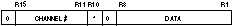
READOUT WORD BIT PATTERN
Single Word Readout Mode
HEADER WORD
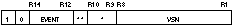
R1 - R8 Virtual Station Number (programmable)
*R9 - R10 Data Shift Value
00 0 Bits (500 psec LSB)
01 1 Bit (1 nsec LSB)
10 2 Bits (2 nsec LSB)
11 3 Bits (4 nsec LSB)
**R11 Edge Recording:
1 = Both Edges Measured
0 = Rising Edge Only
R12 - R14 Buffer Event #
R15 Double Word Indicator
DATA WORD
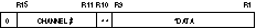
*R1 - R9 Data = 9 Bits (LSB determined by data shift value)
**R10 Rising Edge = 0
Falling Edge = 1
R11-R15 5 Bit Channel Number
DATA WORD
(rising edge only mode)
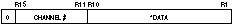
*R1 - R10 Data = 10 Bits (LSB determined by data shift value)
R11-R15 5 Bit Channel Number
Double Word Readout Mode
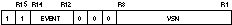
HEADER WORD
R1 - R8 Virtual Station Number
R10 Edge Recording:
Rising Only = 0
Both Edges Measured = 1
R12 - R14 Buffer Event #
R15 Double Word Indicator
FIRST DATA WORD
Most Significant Byte

*R10 Rising Edge = 0
Falling Edge = 1
SECOND DATA WORD
Least Significant Byte
*R10
Rising Edge = 0
Falling Edge = 1
Copyright© January 1997. LeCroy is a registered trademark of LeCroy Corporation.
All rights reserved. Information in this publicaction supersedes all earlier