Key Features
- Compliant with IEEE 802.3-2005 and ANSI INCITS 263-1995 (R2000) Standards (1000Base-T, 100Base-TX, 10Base-T)
- Simple and easy-to-use automated testing and reporting
- The Teledyne LeCroy test fixture (TF-ENET-B) supports complete range of compliance tests without a probe
- Built-in Power Splitter for disturbing signal test
- Mask testing
- "No TX TCLK DUT" support
- Common mode voltage test
QPHY-ENET is a software option package that performs electrical compliance testing for 1000Base-T, 100Base-TX, and 10Base-T standards with Teledyne LeCroy’s QualiPHY automated test and report software.
Select the compliance tests from the QualiPHY menu and the tests will automatically execute, prompting the user with instructions and connection diagrams.
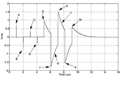
1000Base-T Test Transmitter Test Mode 1 Waveform
When the tests are complete, QualiPHY will generate a test report in PDF, HTML, or XML formats. Jitter and pulse mask tests are performed with automatic waveform alignment, and all test results feature pass/fail indicators corresponding to the standard being tested. 10Base-T pulse mask testing is also supported, using the supplied compliance mask. Teledyne LeCroy's test fixture provides all three standard test loads and conditions as described in the IEEE and ANSI specifications.
1000Base-T Test
Master Jitter Test
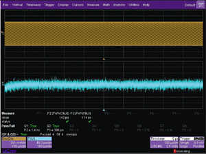
Figure 1: 1000Base-T Mode 2 Test
Figure 1 shows an input signal (Figure 1: upper), and jitter track (Figure 1: lower) which is a plot of jitter value vs. time. The measurement result is shown under the grid. Mode 3 Slave Jitter test is also supported in the package.
Example of Transmitter Test Modes 2 and 3 Waveform
1000Base-T Test Mode 4
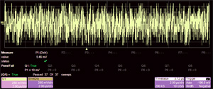
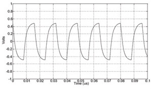
Figure 2: 1000Base-T Mode 4 Test
The transmitter Distortion test is shown in Figure 2. The distortion test measures the error in the signal under test relative to an ideal waveform generated by a mathematical model of the PAM-5 coded signal. A 20.833 MHz disturbing signal, at a level of 5.4 V (2.7 V at the DUT input), can be added. The test uses a high degree of averaging in order to accommodate the 10mV resolution test requirement.
100Base-TX and 10Base-T Tests In QPHY-ENET Sotware Package
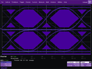
Figure 3: 100Base-TX twisted pair active output interface mask test result.
The QPHY-ENET software package also supports 100Base- TX and 10Base-T tests as defined by IEEE 802.3-2005 and ANSI INCITS 263-1995 (R2000). Figure 3 shows a 100Base-TX Mask test result. The test is commonly used because a compliant signal will not have any mask failures.
10Base-T Differential Output Voltage Mask Test
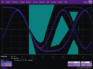
Figure 4: 10Base-T DOV External Mask Test
Figure 4 shows the 10Base-T Differential Output Voltage Mask test. The test is defined as the absolute value of the peak differential voltage measured into a 100 ohm termination. The mask test evaluates the pulse shape.
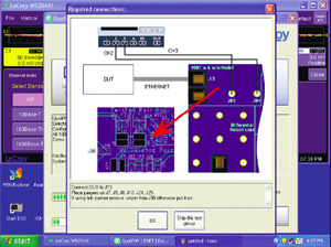
Figure 5: Connection Diagram and Message Box
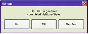
Figure 6: Message Box
Ethernet tests require many test setups and connections. QualiPHY makes it very easy to setup and perform the tests through the use of instructive connection diagrams and message boxes as shown in Figures 5 and 6. The message box under the connection diagram instructs the user how to change jumper pins in order to do the test. Message boxes pop up when test signal needs to be changed by the user.
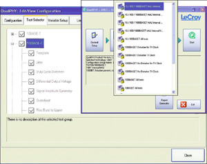
Figure 7: Compliance Test Items Setup and Pre-set Test Procedures Menu
Figure 7 shows Ethernet test items and pre-set test configurations. Test items can be selected from the configuration menu. Users can create customized test sequences by copying the existing configuration and editing. (Users cannot modify pre-set test configurations.)
After the test, the QPHY-ENET software package will generate a test result report as shown in Figure 8. Reports can be generated in HTML, PDF, and XML formats.
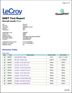
Figure 8: ENET Test Results Report
Each measurement is marked as either Pass or Fail in a summary table. Further information, such as related screen dumps showing the waveform at the time of test, can be found in the Detail section of the report.
Reports give all the relevant information on the instrumentation used to do the compliance test.
TF-ENET-B
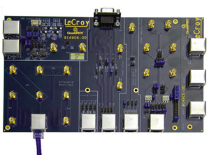
TF-ENET-B: Ethernet test fixture equipped with SMA connection for high signal fidelity. *SMA cable and adapter included with fixture.
TF-ENET-B is required to test all 3 standards (10/100/1000Base-T). All signal connections to the digital oscilloscope use SMA cables in order to avoid any influence from additional circuits such as probes. The test fixture is designed to include –3 dB power splitter for disturbing signal tests in the 1000Base-T. The kit includes 50 ohm terminators (6), 6" Ethernet cable (1) to connect to the DUT, SMA cables (2), and BNC to SMA adapters (2).
| 1000Base-T Tests |
- Mode 1: PDOV, Droop, Pulse Mask
- Mode 2: Master Jitter
- Made 3: Slave Jitter
- Mode 4: Transmitter Distortion
- Common Mode Output Voltage
|
| 100Base-T Tests |
- UTP Differential Output Voltage
- Overshoot
- Signal Amplitude Symmetry
- Risetime Base To Upper
- Falltime Upper To Base
- Risetime Lower To Base
- Falltime Base To Lower
- Rise/Fall Time Symmetry
- Duty Cycle Distortion
- Jitter
- Twisted-Pair Active Output Interface Template
|
| 10Base-T Tests |
- Peak Differential Output Voltage
- Harmonics
- Internal/External MAU Normal
- Internal/External MAU Inverted
- 100 Ohm: TP_IDL & Link Pulse*
- Load 1: TP_IDL & Link Pulse*
- Load 2: TP_IDL & Link Pulse*
- Output Timing Jitter*
- 8.0BT Output Timing Jitter*
- 8.5BT Output Timing Jitter*
- Common Mode Output Voltage
*With & Without Twisted-Pair Model |